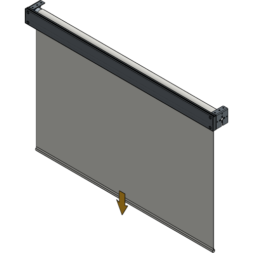
RollUp 300
General
Installation Manual
Installation Manual
No part of this publication may be duplicated or edited in any form or by any means, including any type of electronic or mechanical method without prior written permission from ShowTex.
ShowTex and its employees are fully aware of their task to provide a reliable edition of this document. Nevertheless, they cannot accept any form of liability for the direct or indirect consequences of imperfections that might remain in this edition. The material in this manual is subject to change without notice.
ShowTex warrants that its mechanical and technical products, when delivered in new condition, in original packing, sold directly and used in normal conditions are free from any defects in manufacturing, materials and workmanship. For more information about your local warranty terms, please check our website or contact your local ShowTex office.
All products from the ShowTex Rental range are supposed to be returned in the same state as they were rented. Please treat our products with care, allowing the next user to enjoy the products as much as you did. The rented products are internally checked according to the general rental conditions. Be sure to check our rental guidelines on our website before installing and using this product: ShowTex rental guidelines
Read and understand this user manual before installing and or operating the system. Failure to follow the instructions in this document could result in serious injury!
Following the guidelines of this manual will reduce the risk of damaging the equipment or injuring yourself and the people around you. Nevertheless, ShowTex cannot be held accountable for any use or misuse of the equipment and supplies.
Damage to the system caused by any other method of installation than the one shown in this manual can only be repaired or fixed at the customer’s expense.
As a result of the above warning, any ShowTex product must be installed and operated by a qualified technician who knows its capabilities as well as its limitations.
In case you are uncertain about the eligibility of any hardware in your product, please get in touch with your local ShowTex office to receive additional guidance.
Thank you for choosing for ShowTex and purchasing one of our products. We want to ensure that your experience is as smooth and safe as possible, so we kindly request that you take a few moments to carefully read this manual before installing your new system.
This manual contains important information that will help you comply with health and safety regulations, as well as provide guidance on how to safely install, operate and maintain your product. Our team has taken great care to ensure that this manual is easy to understand and follow, using straightforward language and clear illustrations.
If you have any questions or concerns regarding the installation or use of your product, please feel free to contact your local ShowTex office. Our knowledgeable team members are always available to assist you and answer any questions you may have.
| Article number | Colour | Weight | Length | Tube |
|---|---|---|---|---|
| 8854 4130 7810 | Black | 45.00 kg | 4.00 m | 78 mm |
| 8854 4130 1010 | Black | 50.00 kg | 6.00 m | 100 mm |
| Article number | Colour | Weight |
|---|---|---|
| 0372 0000 1100 | PVC Grey | 0.10 kg |
| Article number | Colour | Weight | Length | ⌀ |
|---|---|---|---|---|
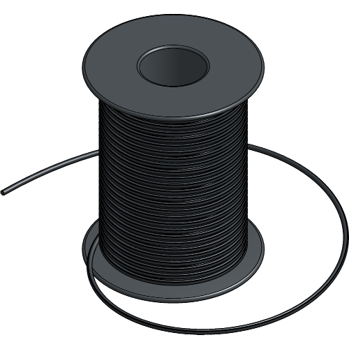
| 7550 0002 0007 | Black | 0.38 kg | 100.00 m | 2 mm |
| 7550 0002 0003 | White | 0.38 kg | 100.00 m | 2 mm |

| Article number | Colour | Weight | WLL |
|---|---|---|---|
| 8700 0680 0757 | Black | 0.18 kg | 100.00 kg |
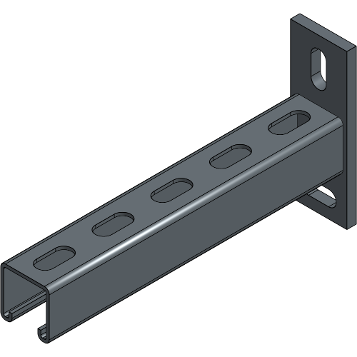
| Article number | Colour | Weight | Length |
|---|---|---|---|
| 8700 0650 0257 | Black | 0.86 kg | 0.25 m |
| 8700 0650 0357 | Black | 1.38 kg | 0.45 m |
| 8700 0650 0607 | Black | 1.74 kg | 0.60 m |
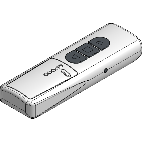
| Article number | Colour | Weight | Channels |
|---|---|---|---|
| 8160 7400 1307 | White | 0.07 kg | 1 |
| 8160 7400 1317 | White | 0.07 kg | 5 |
| 8160 7400 1327 | White | 0.07 kg | 10 |
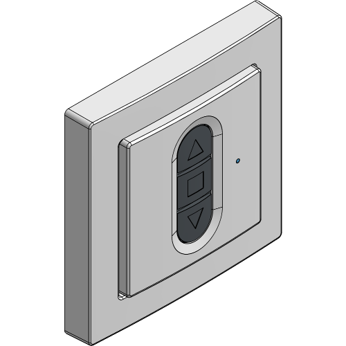
| Article number | Colour | Weight | Channels |
|---|---|---|---|
| 8854 0950 0018 | White | 0.04 kg | 1 |
| 8854 0950 0028 | White | 0.04 kg | 5 |
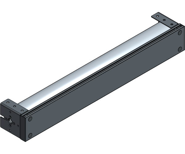
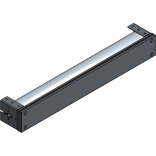
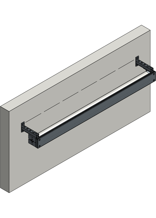
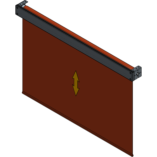
Define the suspension of your ScreenFrame and follow the associated steps.
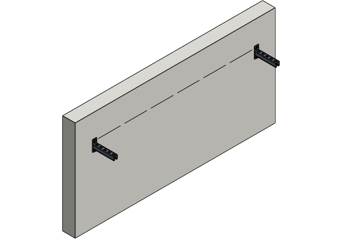
Measure the centre distance of the Wall Brackets and provide leveled suspension points to mount them onto.
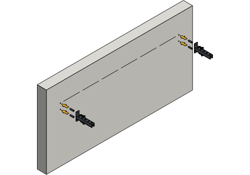
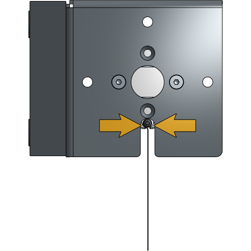
Insert the bolt with spring washer and washer into the top of each Wall Bracket.
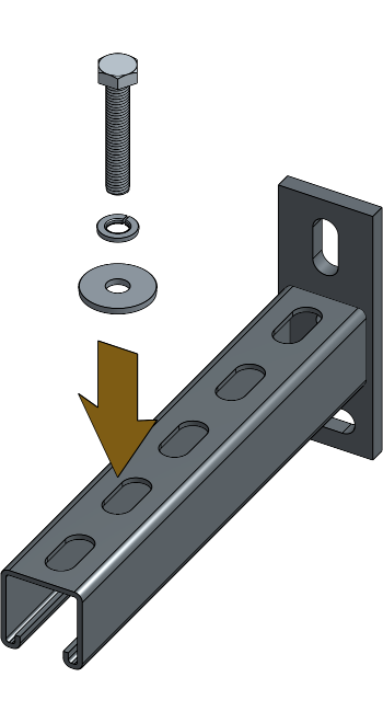
Bolt M10 x 60 + Spring Washer M10 + Washer 10.5 x 50 x 3 + Spring Washer M10 + Hex Nut M10.
Secure side plates to the Wall Brackets by fastening a nut onto each bolt.

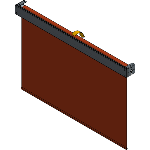
Your RollUp 300 is now suspended with Wall Brackets.
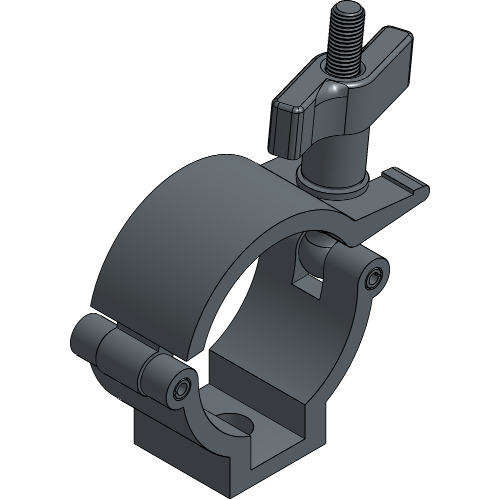
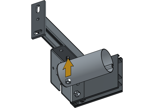
Provide a leveled tube with a diameter of 48-51 mm for suspension.
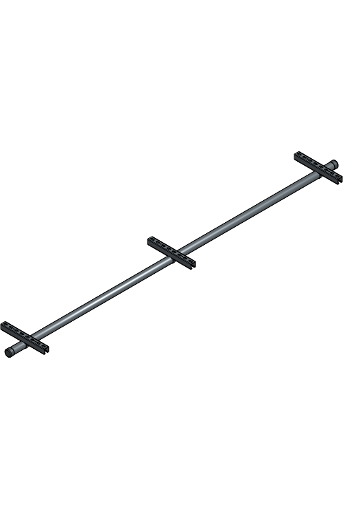
Attach the Half Coupler Clamps on the side plates of the RollUp.
Low Cap Bolt M10 x 2 + Spring Washer M10 + Hex Nut M10.
Clamp the Half Coupler Clamps around the tube and secure them by tightening the wingnut.
Your RollUp 300 is now suspended with Half Coupler Clamps.
Some of the following steps require the Becker Tool app.
Download the Becker Tool app from Google Play on your smartphone.

Download the Becker Tool app from the Apple Store on your smartphone.

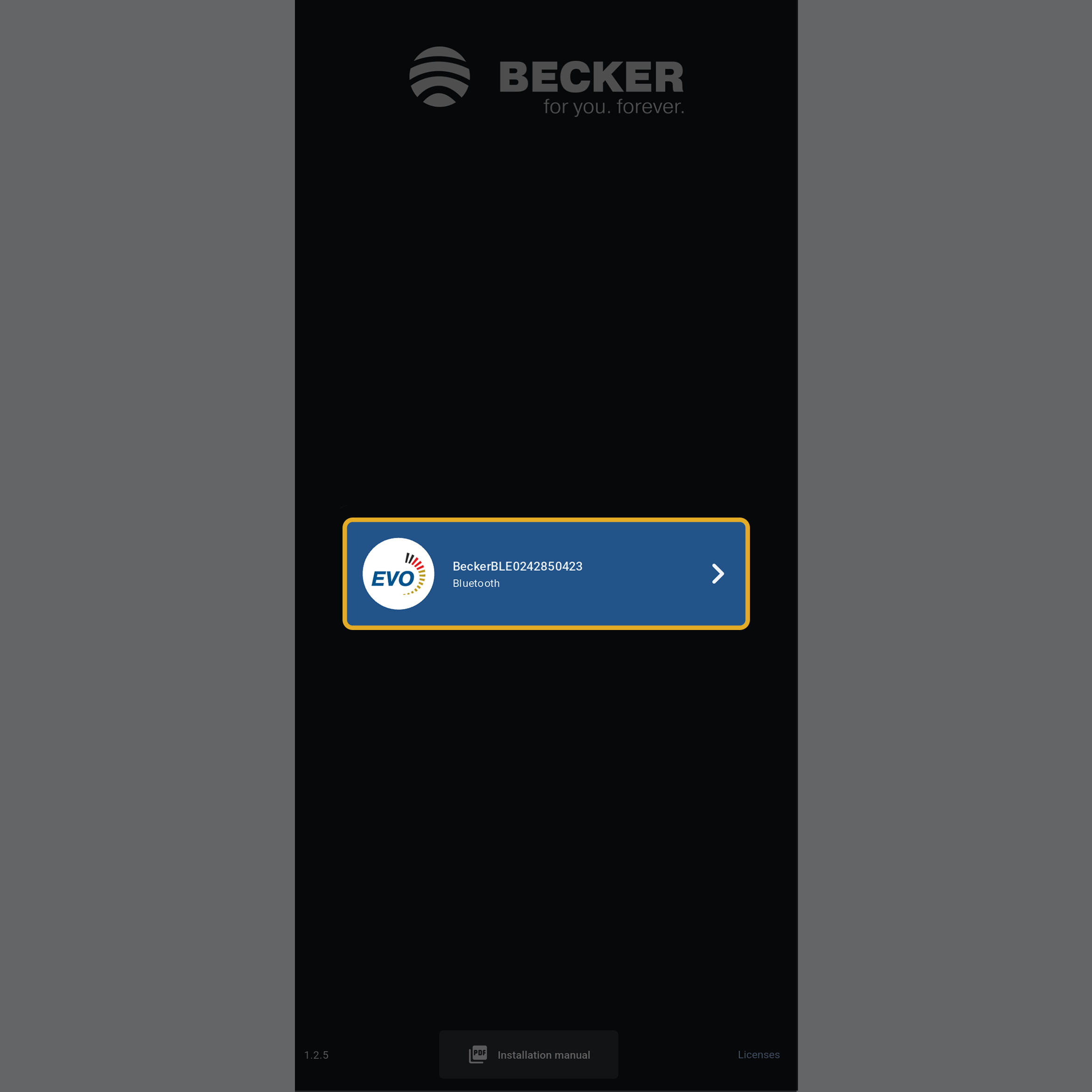
Open the Becker Tool app on your smartphone.

When the roller is at the top limit, operate the roller down for 1 second and back up for 1 second to place it in the learning mode.
Select the roller on the app and fill in the standard code of 123456.
Programming Mode is required for devices not yet configured in the installation or for applying new settings. One of the following two steps is required to enable the programming mode of the RollUp 300.
Switch on the power of the RollUp 300 to enable programming mode for 15 minutes.
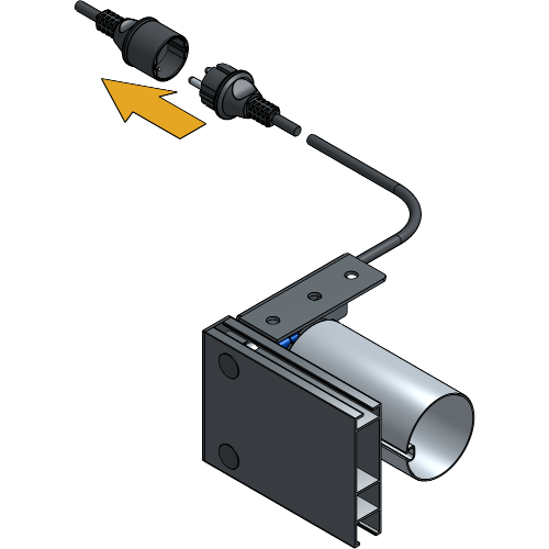
If the power is already on, place the switch with antenna symbol to the middle to enable programming mode for 15 minutes.

If the swith is already in the middle position, place it in the outer position and then back to the middle position to enable programming mode.
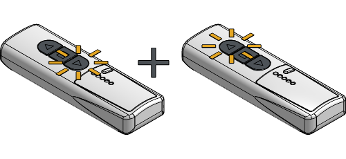
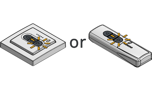
The following steps apply to both the RF Remote and RF Wall Switch, as the configuration process is identical.
Press and hold the programming button on the master transmitter (RF Remote or RF Wall Switch) for about 3 seconds. The RollUp will confirm the action by performing a short movement.
![]()
If the new transmitter has multiple channels, press the function button to select the desired channel to program the RollUp.
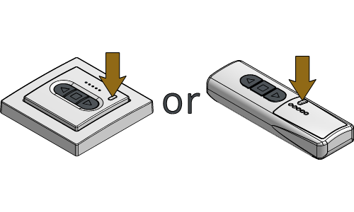
Press and hold the programming button on the new transmitter for about 3 seconds. The RollUp will confirm the action by performing a short movement.
![]()
Press and hold the programming button on the new transmitter for about 3 seconds for a second time. The RollUp will confirm the action by performing a short movement, and the new transmitter will be configured.
![]()
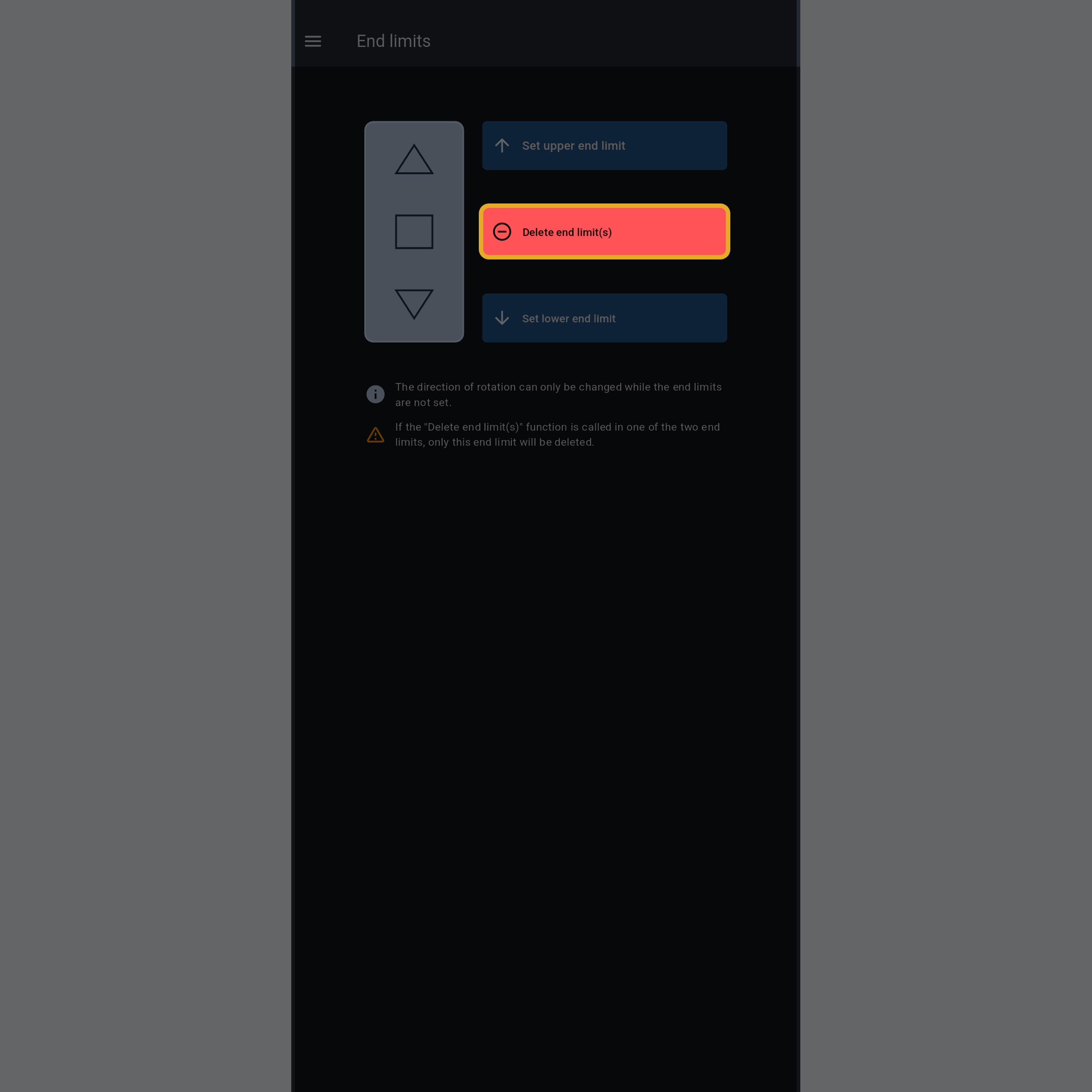
The rotation direction can only be adjusted if no end positions are configured.
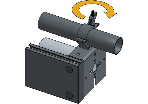
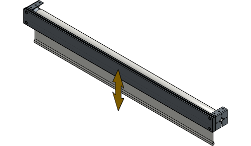
Press the ▲ or
▼ button and operate the roller and check
the rotation direction.
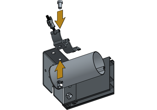
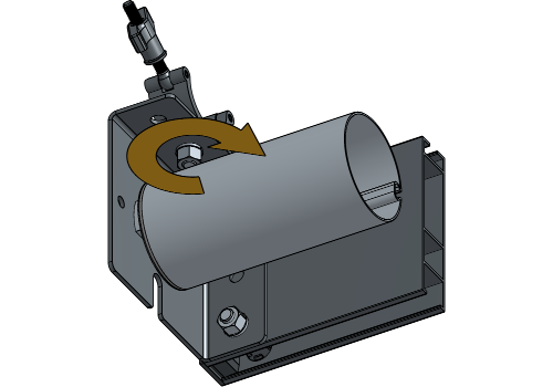
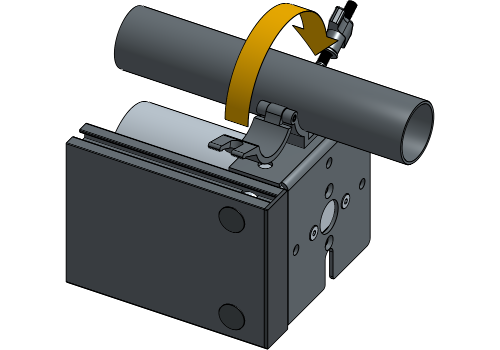
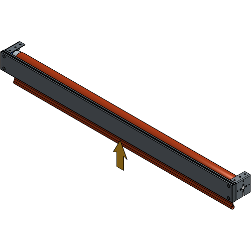
If the fabric rolls in the opposite direction, slide the direction switch on the motor to the opposite position.
Operate the roller again to varify that the rotation direction is now correct.
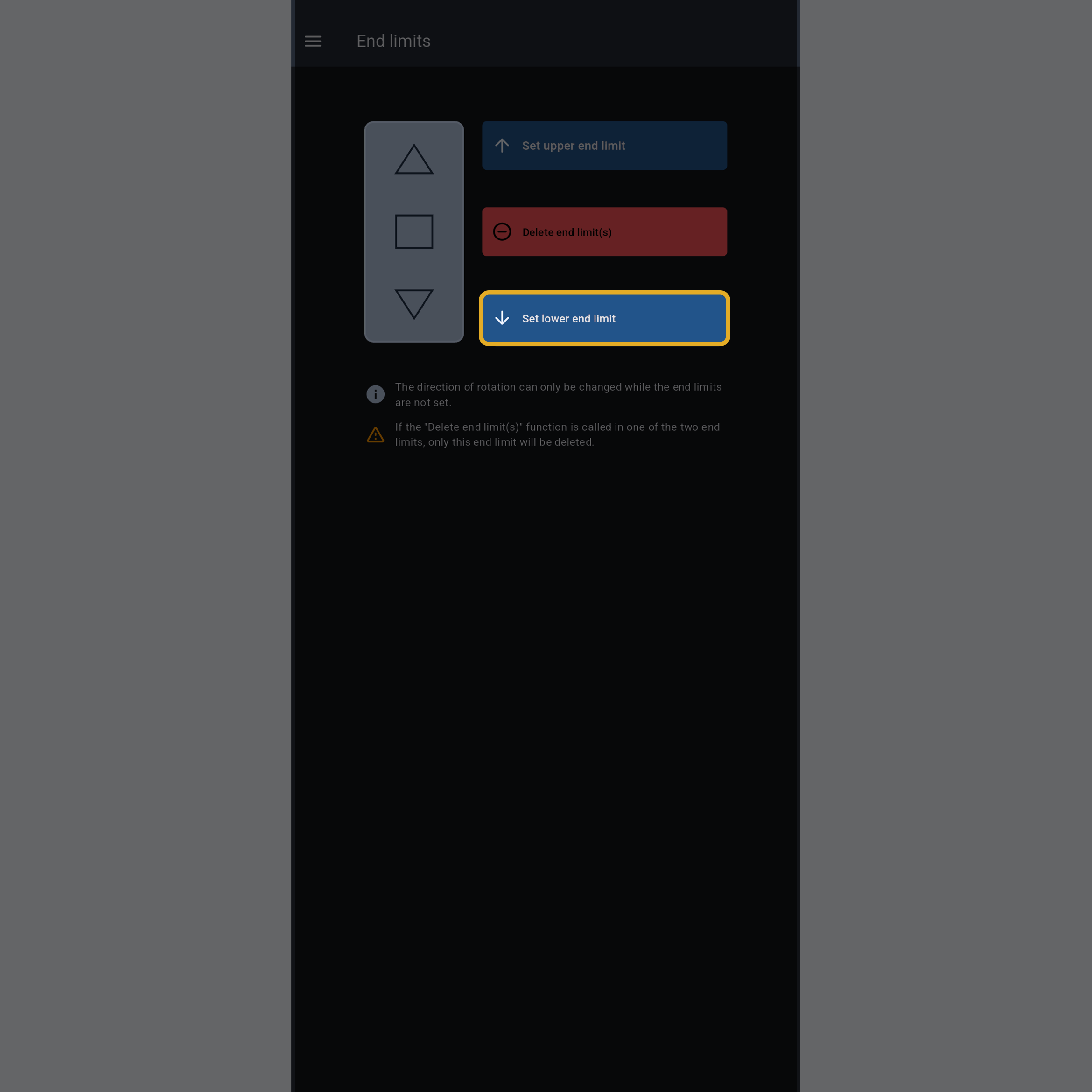
Navigate to the End limits tab on the Becker Tool app.
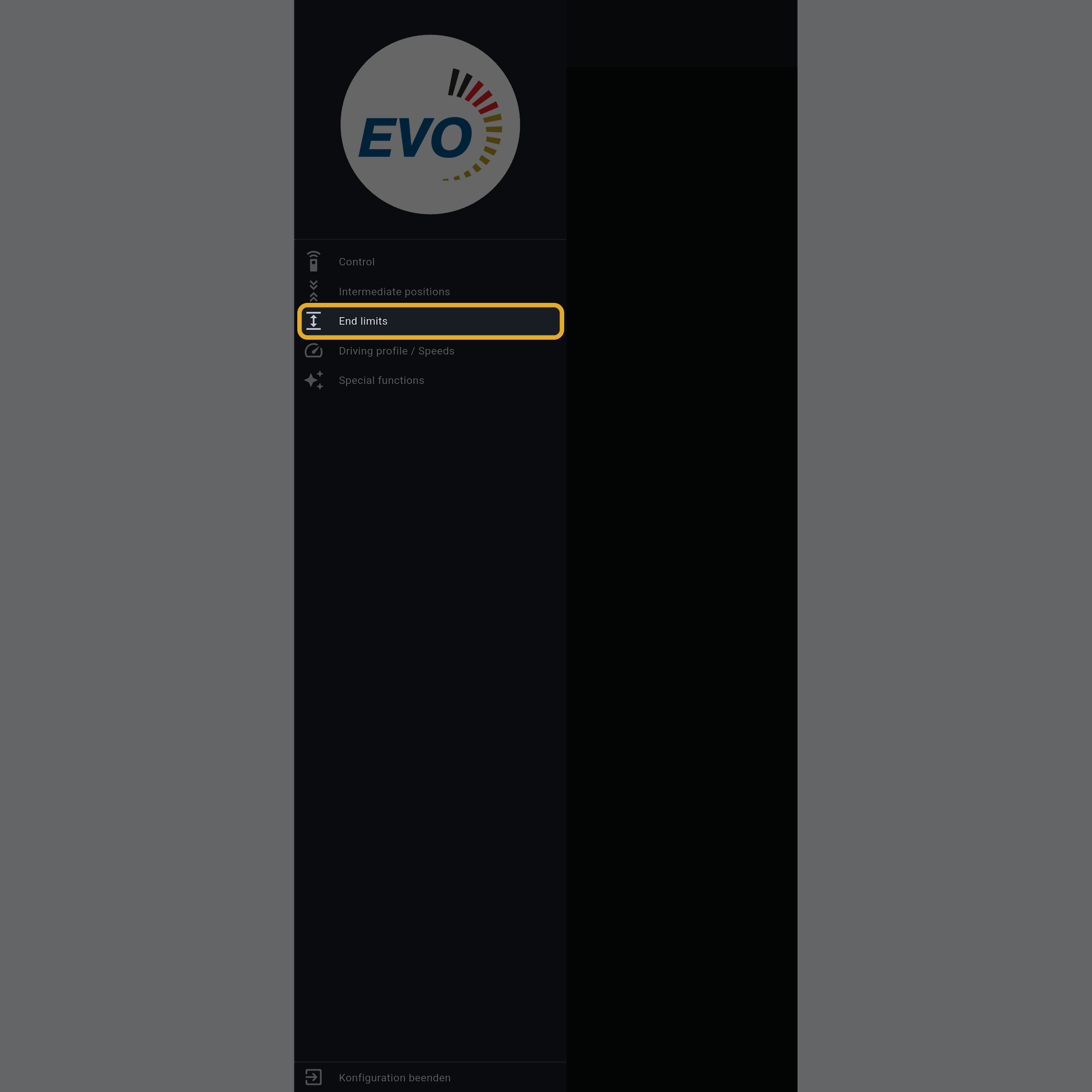
Press “Delete end limit(s)” to delete both the upper and lower limit.
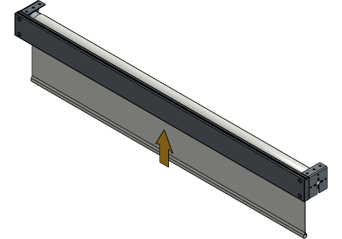
Operate the roller to unroll the fabric completely.
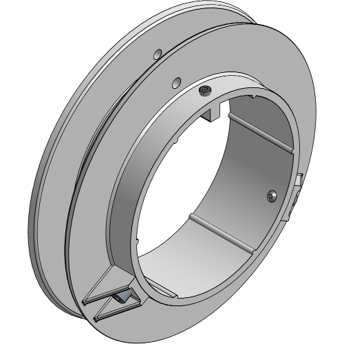
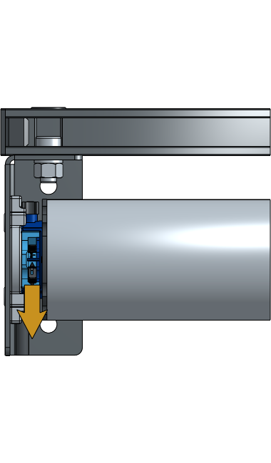
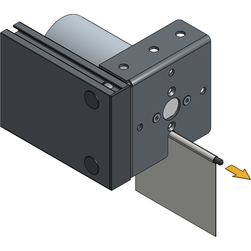
Align the keder slot of the tube with the slot on the side plate.
Slide the fabric out of the keder slot of the tube.
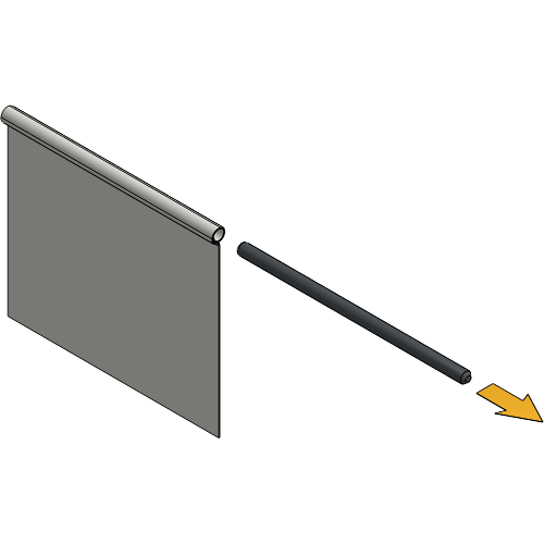
Remove the fibreglass rod from the open pocket at the top of the fabric.
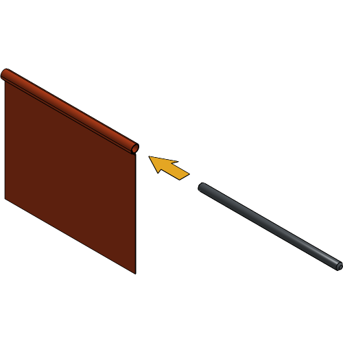
Insert the fibreglass rod into the open pocket of the new fabric.
Slide the fabric into the keder slot of the tube with the correct side facing the front.
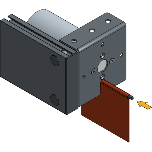
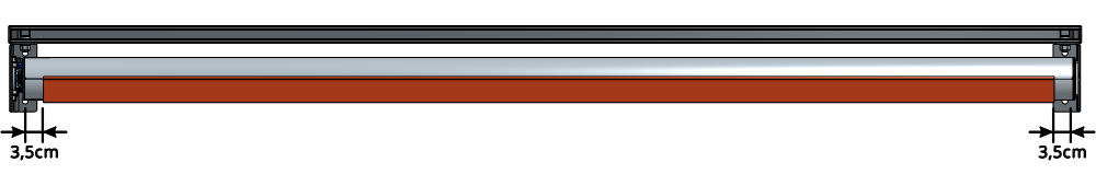
The fabric should be positioned in the centre of the RollUp with about 3.5 cm margin on each side.
Operate the roller to roll up the fabric until at least two full turns of fabric are wrapped around the roller.
Press “Set lower end limit” to define the lower limit of the roller.
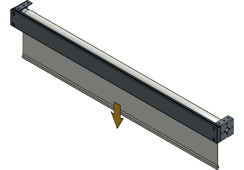
Operate the roller to roll up the fabric until the bottom of the fabric is approximately 10 cm below the RollUp.
Press “Set upper end limit” to define the upper limit of the roller.
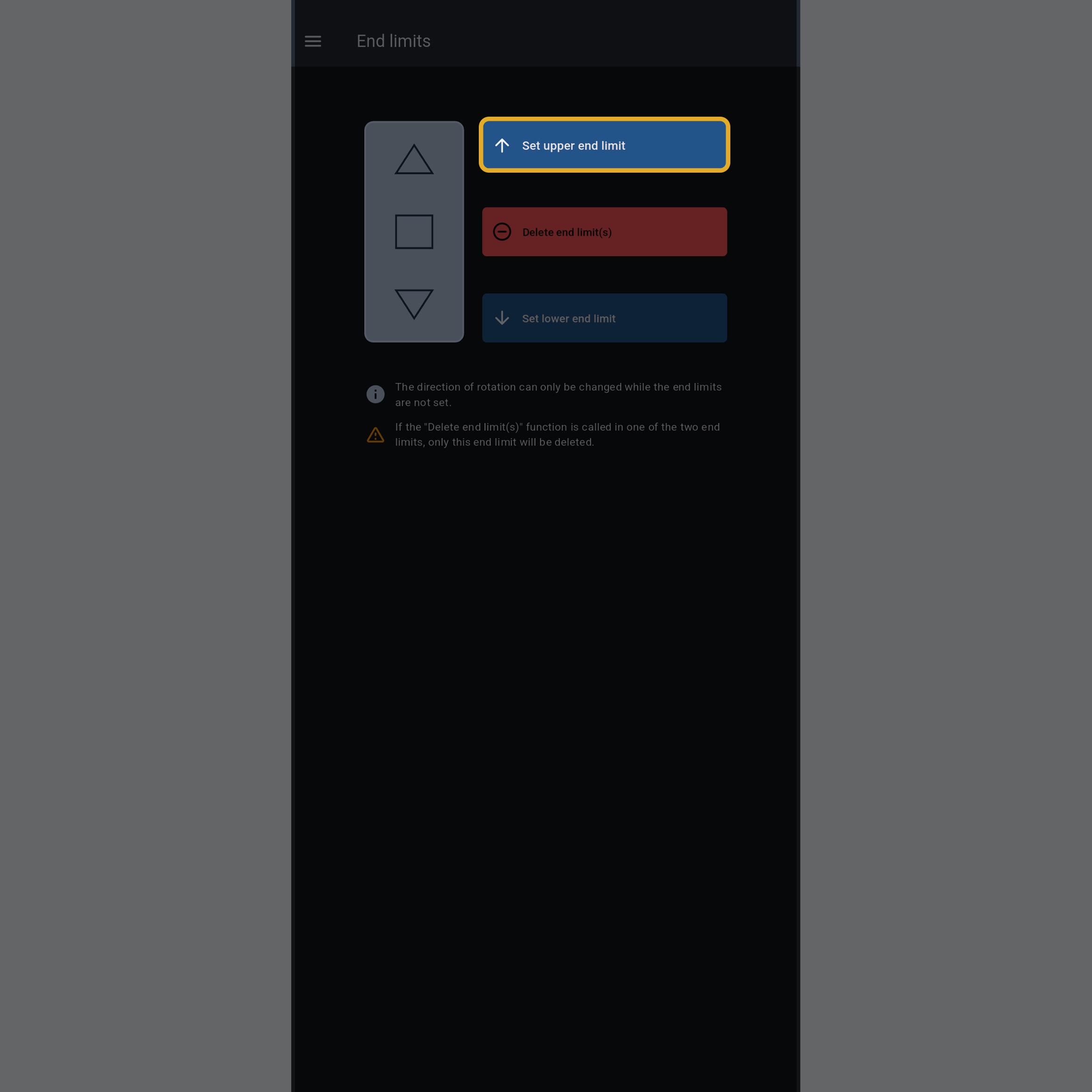
Operate the roller up and down to verify that both limits are correctly set.
Your RollUp 300 is now completely configured and ready to use!
For more technical assistance, please contact your local ShowTex
office.
The address and contact information can be found on our website:
www.showtex.com