HiSpeed RollUp
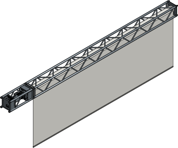
Truss Roller with HiSpeed Motor 8000
Installation Manual
Installation Manual
No part of this publication may be duplicated or edited in any form or by any means, including any type of electronic or mechanical method without prior written permission from ShowTex.
ShowTex and its employees are fully aware of their task to provide a reliable edition of this document. Nevertheless, they cannot accept any form of liability for the direct or indirect consequences of imperfections that might remain in this edition. The material in this manual is subject to change without notice.
ShowTex warrants that its mechanical and technical products, when delivered in new condition, in original packing, sold directly and used in normal conditions are free from any defects in manufacturing, materials and workmanship. For more information about your local warranty terms, please check our website or contact your local ShowTex office.
All products from the ShowTex Rental range are supposed to be returned in the same state as they were rented. Please treat our products with care, allowing the next user to enjoy the products as much as you did. The rented products are internally checked according to the general rental conditions. Be sure to check our rental guidelines on our website before installing and using this product: ShowTex rental guidelines
Read and understand this user manual before installing and or operating the system. Failure to follow the instructions in this document could result in serious injury!
Following the guidelines of this manual will reduce the risk of damaging the equipment or injuring yourself and the people around you. Nevertheless, ShowTex cannot be held accountable for any use or misuse of the equipment and supplies.
Damage to the system caused by any other method of installation than the one shown in this manual can only be repaired or fixed at the customer’s expense.
As a result of the above warning, any ShowTex product must be installed and operated by a qualified technician who knows its capabilities as well as its limitations.
In case you are uncertain about the eligibility of any hardware in your product, please get in touch with your local ShowTex office to receive additional guidance.
Thank you for choosing for ShowTex and purchasing one of our products. We want to ensure that your experience is as smooth and safe as possible, so we kindly request that you take a few moments to carefully read this manual before installing your new system.
This manual contains important information that will help you comply with health and safety regulations, as well as provide guidance on how to safely install, operate and maintain your product. Our team has taken great care to ensure that this manual is easy to understand and follow, using straightforward language and clear illustrations.
If you have any questions or concerns regarding the installation or use of your product, please feel free to contact your local ShowTex office. Our knowledgeable team members are always available to assist you and answer any questions you may have.
Periodic, regularly scheduled maintenance inspections are essential for every product. Each system contains components that must be inspected, adjusted, maintained, or replaced over time. Establishing a consistent maintenance routine ensures long-term safety, reliability, and optimal performance.
Please follow the steps outlined in the Care & Maintenance schedule provided for this product. These steps represent the minimum required maintenance program.
| Article number | Colour | Weight | Length |
|---|---|---|---|
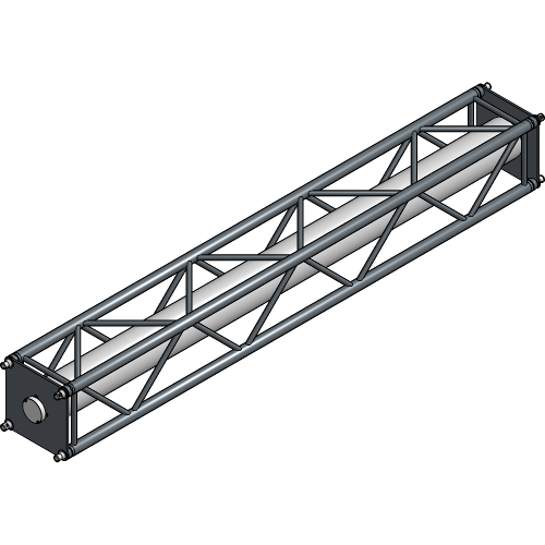
| 8140 3115 3007 | Black | 125.00 kg | 3.00 m |
| 8140 3115 6007 | Black | 175.00 kg | 6.00 m |
| 8140 3115 9007 | Black | 225.00 kg | 9.00 m |
| Article number | Colour | Weight | Length |
|---|---|---|---|
| 8140 3112 1047 | Black | 100.00 kg | 1.00 m |
| Article number | Colour | Weight |
|---|---|---|
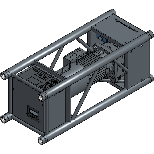
| 8140 2263 0007 | Black | 24.20 kg |
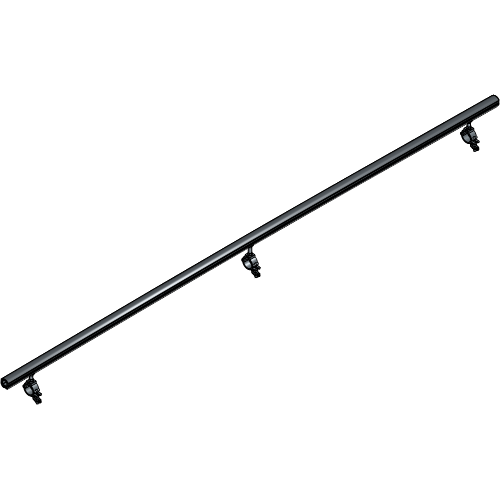
| Article number | Colour | Weight | Length |
|---|---|---|---|
| 8140 3120 3007 | Black | 4.00 kg | 3.00 m |
| 8140 3120 6007 | Black | 8.00 kg | 6.00 m |
| 8140 3120 9007 | Black | 12.00 kg | 9.00 m |
| Article number | Colour | Weight |
|---|---|---|
| 8140 2247 0124 | Aluminium | 0.18 kg |
| Article number | Colour | Weight |
|---|---|---|
| 8140 2247 0224 | Aluminium | 0.23 kg |
| Article number | Colour | Weight |
|---|---|---|
| 8140 2247 0004 | Aluminium | 0.11 kg |
| Article number | Colour | Weight |
|---|---|---|
| 8140 3116 3027 | Aluminium | 0.50 kg |
| Article number | Colour | Weight |
|---|---|---|
| 8140 2247 0014 | Aluminium | 0.04 kg |
| Article number | Colour | Weight |
|---|---|---|
| 8140 2253 0001 | Aluminium | 0.05 kg |

| Article number | Colour | Weight |
|---|---|---|
| 8140 9999 0007 | Red | 0.05 kg |
| Article number | Colour | Weight |
|---|---|---|
| 8140 3117 0037 | Black | 0.75 kg |
| Article number | Weight | Length |
|---|---|---|
| 8145 0912 0017 | 0.78 kg | 2.00 m |

| Article number | Weight | Length |
|---|---|---|
| 8140 3117 0027 | 3.28 kg | 25.00 m |
| Article number | Weight | Length | Connector |
|---|---|---|---|
| 8140 3117 0047 | 1.20 kg | 25.00 m | XLR 3 |

| Article number | Weight | Length | Connector |
|---|---|---|---|
| 8050 7220 5107 | 0.38 kg | 10.00 m | XLR 5 |
| 8050 7220 5127 | 0.40 kg | 12.50 m | XLR 5 |
| Article number | Weight | Length | Cable |
|---|---|---|---|
| 8140 3117 0227 | 0.88 kg | 30.00 m | Cat 6 Shielded |
| Article number | Colour | Weight |
|---|---|---|
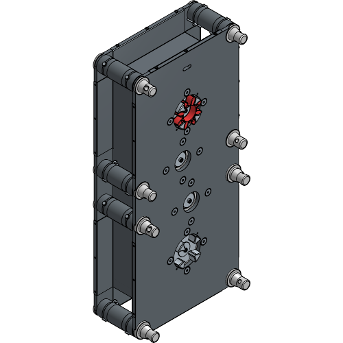
| 8140 7260 0040 | Black | 70.00 kg |
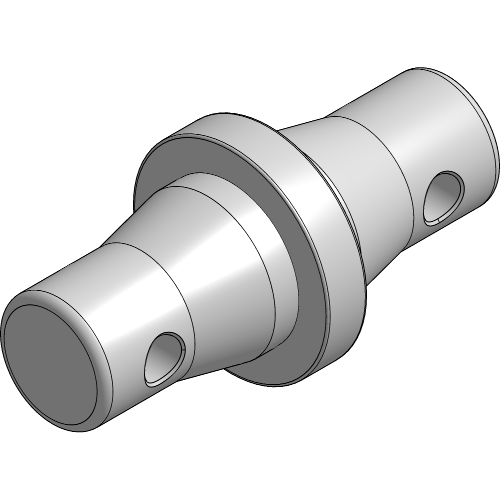
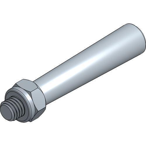
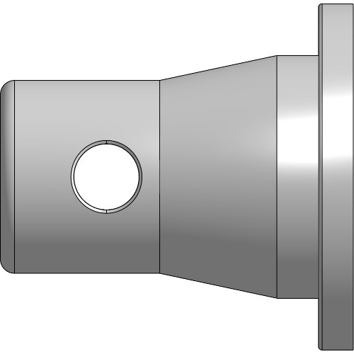
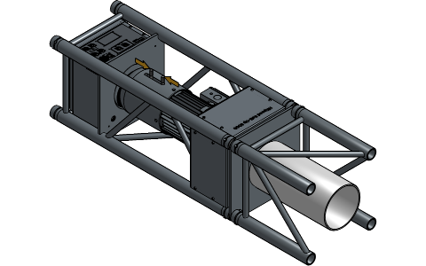
Conical Couplers Truss-Roll are used to connect a Truss Roller to the HiSpeed Motor 8000. The Truss-Roll Couplers are asymmetrical as one side has a conical and a cylindrical shape and mates with the truss. The other side is fully conical shaped and mates with the truss roller.
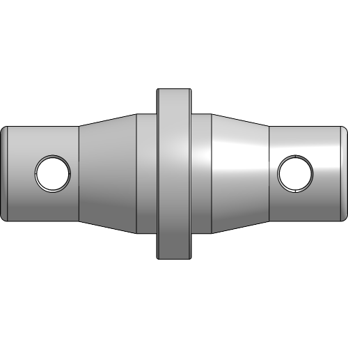
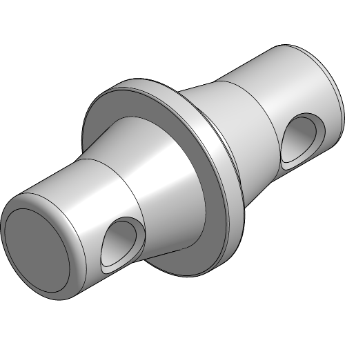
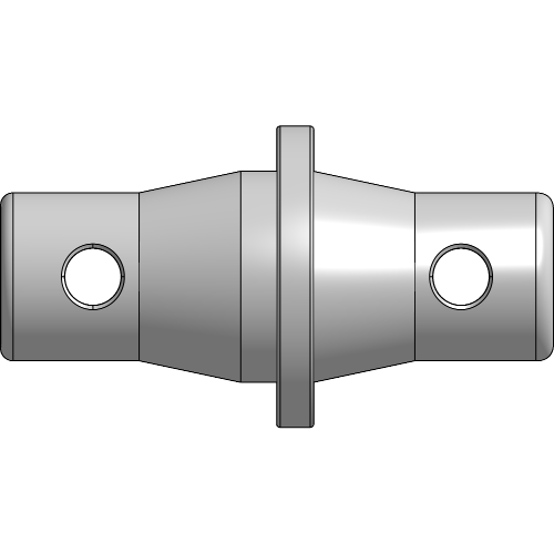
Conical Couplers Roll-Roll are used either to connect two Truss Rollers, a Truss Roller and the HiSpeed Motor 3000 or the Angled Transmission. The Roll-Roll Couplers are symmetrically shaped with on both sides a conical and cylindrical shape.
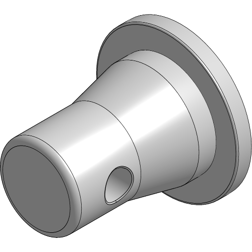
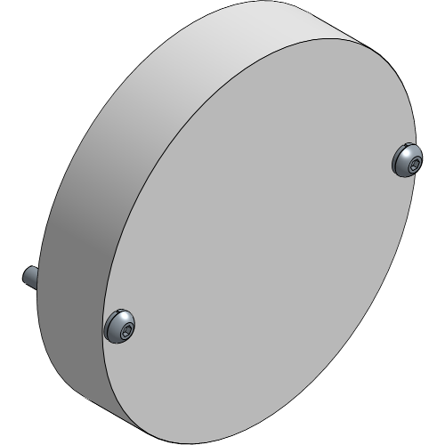
Conical End Pieces are used for protection of the Truss and are removed when the Truss Roller gets coupled. For transport the Conical End Pieces need to be re-inserted at all times.
If the HiSpeed setup was delivered assembled, go to chapter Rigging the Truss Roller.
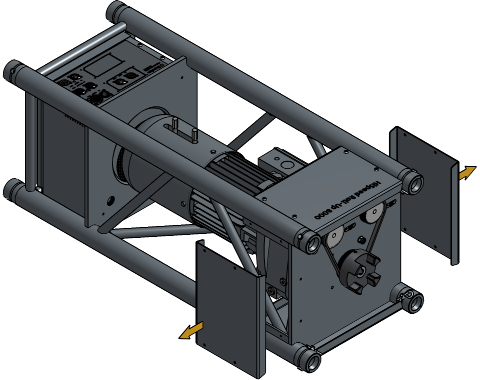
Unfasten the bolts and remove the side cover plates of the motor.

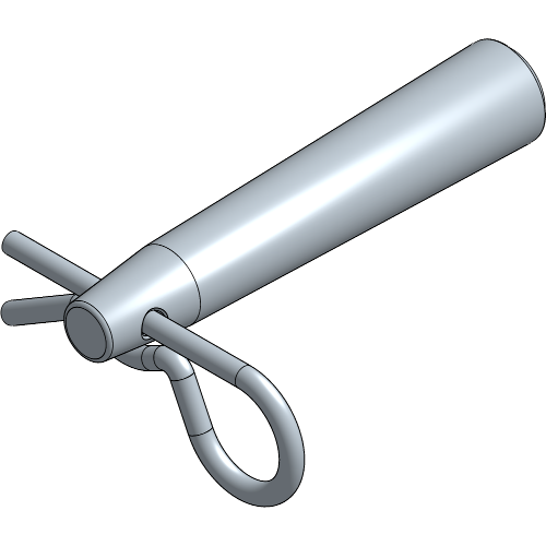
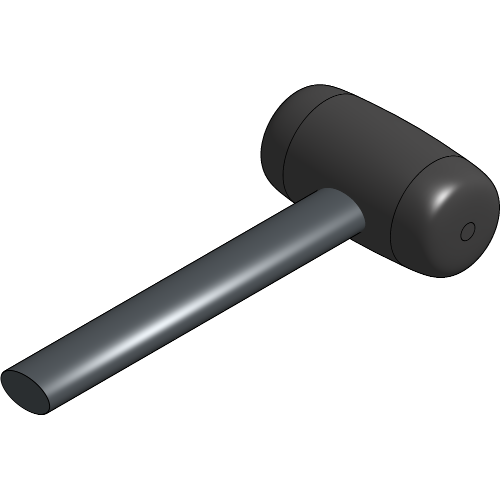
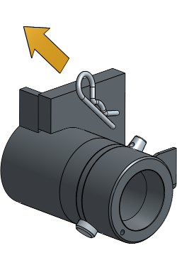
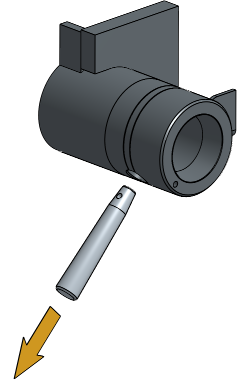
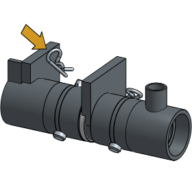
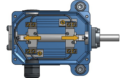
Take out the 4 Safety Clips and hammer the Pins out of the motor.
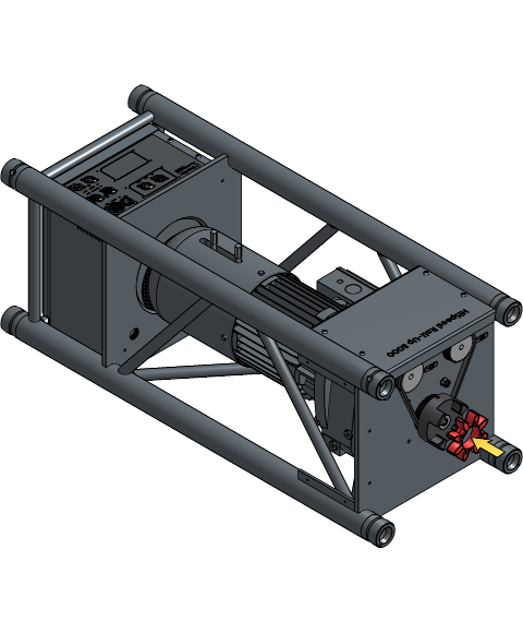
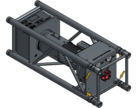
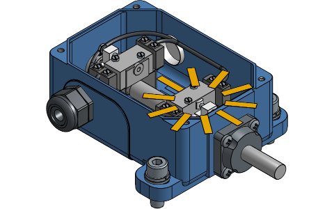
Place the Coupling Spider on the coupling jaw of the motor.
Align the coupling jaw of the Truss Roller with the coupling jaw of the motor and insert the Conical Couplers into the Truss Roller.
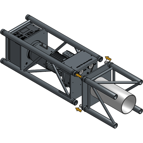
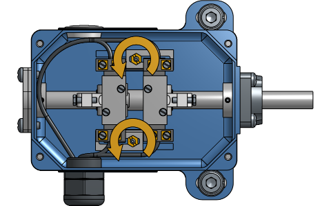
The coupling jaw of the motor and Truss Roller need to be aligned in order to couple them. If they are not aligned, rotate the Truss Roller until they are aligned
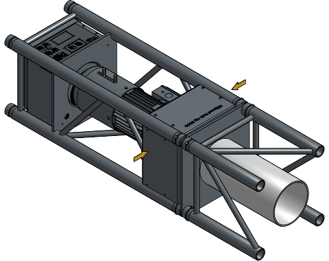
Insert a Pin with the hole lined up vertically in all 4 holes of the motor and hammer it in to secure all Conical Couplers.


Insert a Safety Clip in all 4 holes of the Pins.
Place both side plates of the motor back on and fasten the bolts.

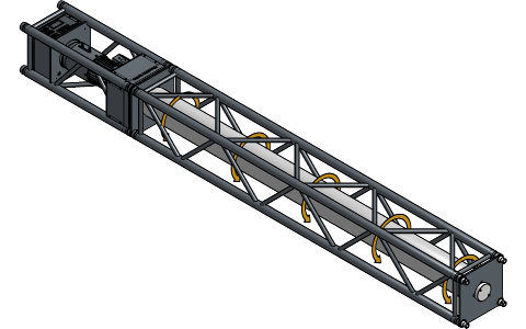
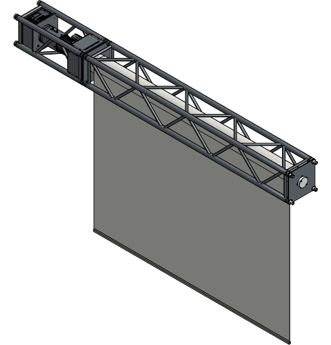
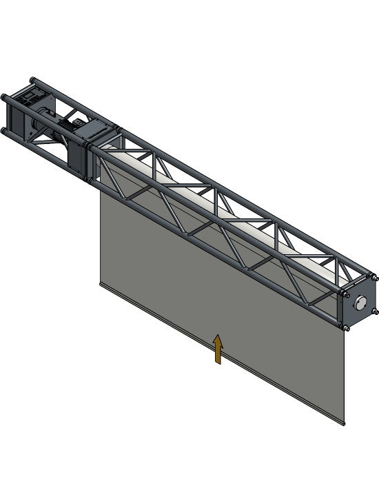
Provide the rigging points that are required for your setup. These are different for each Truss Roller size and depend on the truss junctions.
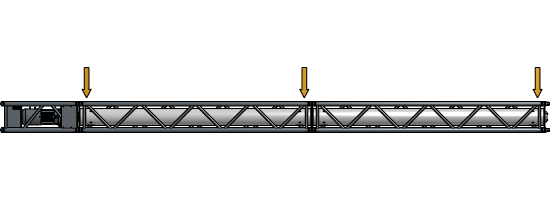
A rigging point must be provided at each truss junction. For more information about the correct rigging points for each setup, consult the Technical Data Sheet.
For extra information and details about the electrical wiring and connectors, consult the Technical Data Sheet of the HiSpeed Motor 8000.
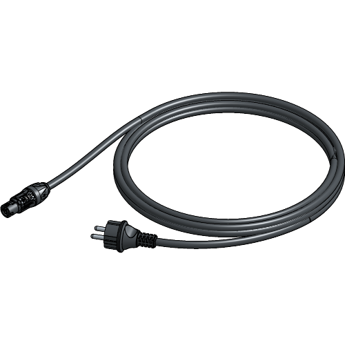
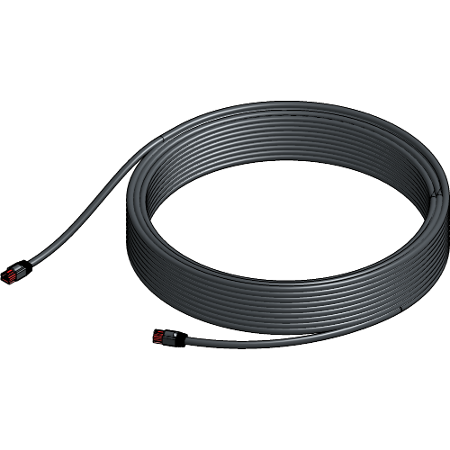
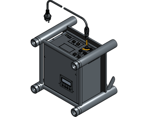
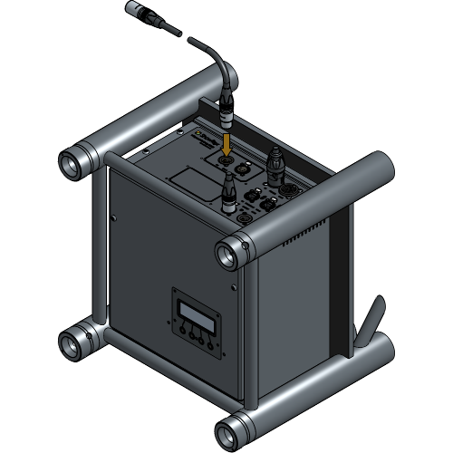
Plug the Power Supply Cable into the motor. The Power Supply Cable can be extended with Power Extension Cables as needed.

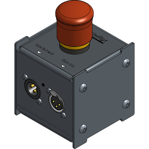
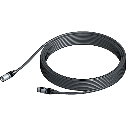
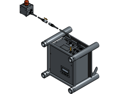
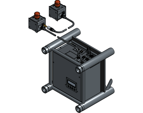
Plug the Emergency Stop Cable into the motor.
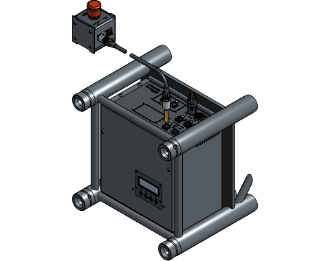
Always keep the Emergency Stop within easy reach.
Connect additional Emergency Stops to the first Emergency stop as needed.
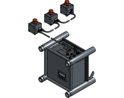
Ensure that all plugs are in their locked position. Having cables in an unlocked position may result in poor contact or no contact. If any cables are in an unlocked position, insert the plug and twist to lock the cable.
If the HiSpeed setup is pre-configured at ShowTex and delivered disassembled or if the HiSpeed setup is delivered fully assembled, the hard limits are already set to the correct position! Go to System Startup.
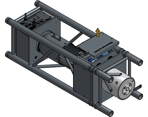
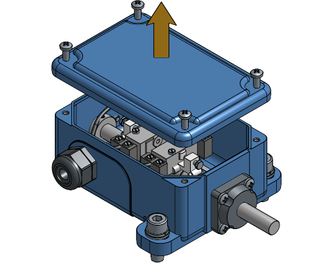
Unfasten the bolts and remove the top cover plate of the motor.

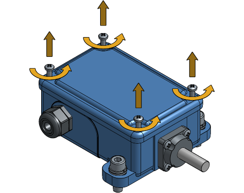
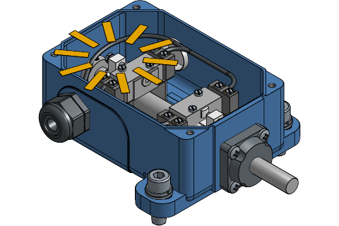
Unfasten the bolts of the hard limits cover and remove it.
The motor mounting side determines which limit switch is the high limit and which limit is the low limit.
The following setups explain how to determine the low limit switch, which should be set first in cases where no screen is attached yet. If you have a pre-configured setup and need to adjust the hard limits, it’s more convenient to adjust the high limit first, as the screen is rolled up when delivered.
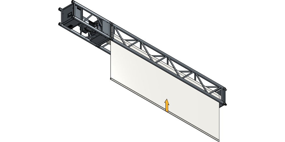
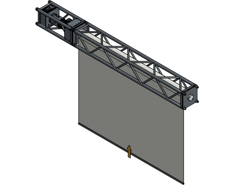
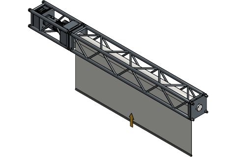
With the front side of the fabric showing, the motor mounted on the left and the fabric rolling up towards the front, the limit switch closer the coupling jaw is the low limit. This is a correct setup for projection screens.
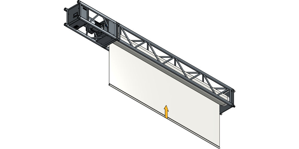
With the front side of the fabric showing, the motor mounted on the left and the fabric rolling up towards the back, the limit switch further away from the coupling jaw is the low limit.
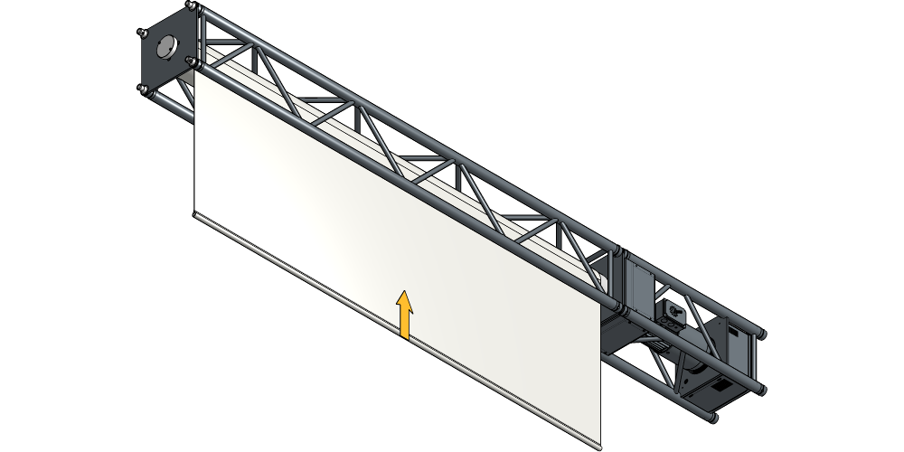
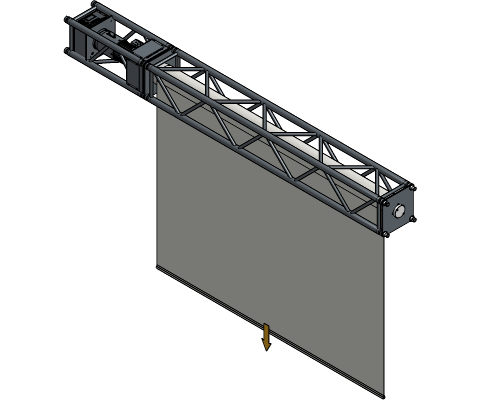
With the front side of the fabric showing, the motor mounted on the right and the fabric rolling up towards the front, the limit switch further away the coupling jaw is the low limit. This is a correct setup for projection screens.

With the front side of the fabric showing, the motor mounted on the right and the fabric rolling up towards the back, the limit switch closer the coupling jaw is the low limit.
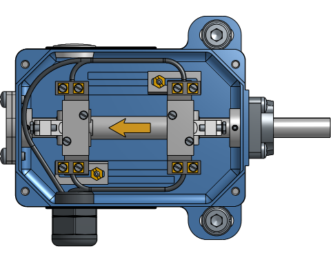
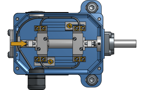
Loosen the copper nuts of each switch and place them at their outer position.
Place the first switch 2-3 mm of the end of its range. Tighten the copper nut. This switch will determine the unrolled position.


Take extra caution when tightening the copper nuts, over-tightening them can break the threaded stud.
Press the ☰ key to activate the LCD screen. Navigate to
Reference move and press the
✔ key. Press and hold the
▲ and ▼ key
to operate the roller up and down in the following steps.


Operate the roller down with the ▼
button on the LCD screen until the round shuttle engages the limit
switch, resulting in a clicking sound. The roller should stop
automatically.
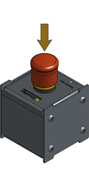
Push the Emergency Stop button for the next steps. This will prevent the motor from moving unexpectedly.
Squeeze the brake handles towards each other and unroll two full turns.
Attach the screen onto the roller.
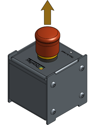
Release the Emergency Stop button by pulling it back up.
Clear the error of the Emergency Stop Unit being engaged.
Navigate to Clear errors and press the
✔ key. Press the
+ key to see
Yes and validate with the
✔ key.


Every time the Emergency Stop Unit has been engaged this step must be repeated for the motor to be operational again.
Operate the roller up with the ▲
button on the LCD screen until the round shuttle disengages the limit
switch, resulting in a clicking sound. This can take up to three full
turns above the previously set position.
Operate the roller down to check if the limit switch is set correctly. When the screen is rolled down completely, check if there are at least two full turns are on the roller.
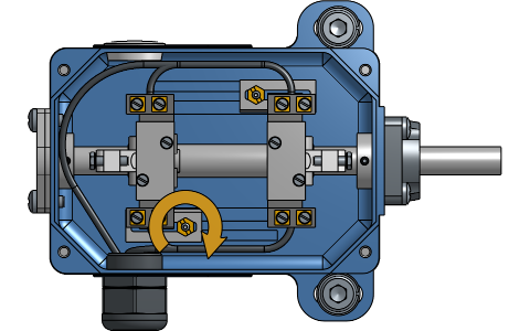
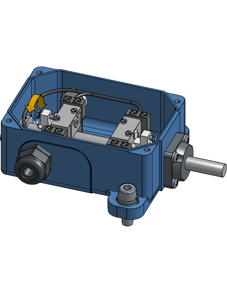
Loosen the screw with a long nose pliers to make the screen stop at a higher position or tighten the screw to make the screen stop at a lower position.

Avoid turning the screw too far in or out, putting it back in its correct position is difficult.
Roll up the screen until about 1.5 meters before the stop point that will be needed.
Place the second switch as close as possible to the round shuttle without hearing a clicking sound and tighten the copper nut. This switch will determine the rolled-up position.
Take extra caution when tightening the copper nuts, over-tightening them can break the threaded stud.
Operate the roller up until the round shuttle engages the limit switch, resulting in a clicking sound. The roller should stop automatically.
Check if the screen is rolled up far enough. Loosen the screw with a long nose pliers to make the screen stop at a lower position or tighten the screw to make the screen stop at a higher position.
Avoid turning the screw too far in or out, putting it back in its correct position is difficult.
Place the hard limits cover back and tighten the bolts.
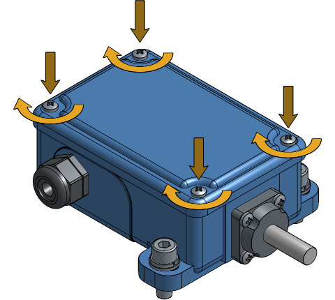
Place the top cover plate of the motor back and tighten the bolts.

The HiSpeed Motor 8000 has an embedded LCD screen on its outer end.
With associated buttons it’s possible to access statuses and
configuration settings. To light up the LCD screen, press the
☰ button.
Navigate to
Config > Motion > Drum type. Use the
+ and − keys
to select the correct drum type. Validate with the ✔
key.

Navigate to Reset. Use the
+ key to select “Yes” and Validate with
the ✔ key.

The correct drum type must always be set. Setting an incorrect drum type may result in mechanical issues and safety hazards.
This chapter is about setting the soft limits with the embedded LCD screen on the motor. To set the soft limits of your HiSpeed Motor 8000 with the UMC software, refer to Installation Manual - First Use.
Navigate to Reference move. Press
and hold the ▲ or
▼ key to move the screen to the desired
“high” position. The status should be
STS: Ready. If not, check if the Emergency
Stop Unit has been disengaged.

Depending on how the motor reacted in the previous step, you will
need to invert the rolling direction. Navigate to
Config > Motion > Invert motion. Use
the + key to select “On” and validate with
the ✔ key.

Navigate to
Config > Motion > Set home. Use the
+ key to select “Yes” and validate with
the ✔ key.

Navigate to
Config > Motion > High limit. Press
the + and − key at the same
time to get the current position. Validate the new soft limit with the
✔ key.

Navigate back to Reference move.
Press and hold the ▼ key to move the
screen to the desired “low” position.

Navigate to
Config > Motion > Low limit. Press
the + and −
key at the same time to get the current position. Validate the new soft
limit with the ✔ key.

| Channel offset | Function | Range |
|---|---|---|
0 |
Position (coarse) | 0 - 255 |
1 |
Position (fine) | 0 - 255 |
2 |
Speed | 0 - 255 |
3 |
Command | Refer to Command Channel Values |
Channel offset must be added to the configured DMX address. Position
is calculated using two DMX channels, resulting in a total range of
0 - 65536. This gives a resolution of
0.0015%. For screen of 25 meters high, this is 0.4 millimeter per DMX
step.
| Value range (raw) | Value range (%) | Function |
|---|---|---|
0 - 126 |
0% - 49% |
Disable |
127 - 240 |
50% - 94% |
Enable |
241 - 255 |
95% - 100% |
Disable |
Having a Disable function at the end of
the DMX range allows safe behavior when a lighting desk sends a full-on
DMX packet. In that case, the system safely stops.
In case of the Emergency Stop being pressed, the motor will generate
an error. To resume operation, both speed and command channel must be
held to 0 for a minimal period of
5 seconds.
It is not possible to reset any other type of error using the DMX communication bus.
A new DMX address is instantly applied. The user must ensure that the data sent to the new DMX address will not result in unwanted motion. It is advised to plug out the DMX cable for safety measures if it is already plugged in.
Starting from the status screen, navigate to
Config > DMX > DMX address and press
the ✔ key.

Input the new DMX address using the
+ and - keys
and validate with the ✔ key. The new DMX
address is now effective.

It is possible to set the DMX address to
0. Doing so will disable entire control
over the DMX lightning desk.
Plug the DMX Cable into the motor.
Your HiSpeed RollUp Truss Roller setup with HiSpeed Motor 8000 is now completely installed and ready to use!
For more technical assistance, please contact your local ShowTex
office.
The address and contact information can be found on our website:
www.showtex.com